Buy FCC4 here
Choose your FCC4 fast clock controller here. Buy the FCC4 assembled, tested, and ready to go, or choose the kit and assemble it yourself.
Assembling the FCC4 kit is straightforward, but requires attention to detail and the ability to solder electronic components onto a circuit board using a low-wattage soldering iron. These assembly instructions from the user manual can help you decide whether to order the FCC4 fully assembled or as a kit.
Be sure to order clock movements before you check out.
View Cart to change quantity or check out.
|
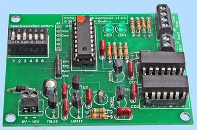
FCC4 Assembled
$130.00
Click the Add to Cart button to buy your FCC4 completely assembled and tested.
You provide an 8VDC - 10VDC power supply, optional control switches, and a case if one is desired. Please read the user manual.
|
View Cart to change quantity or check out.
|
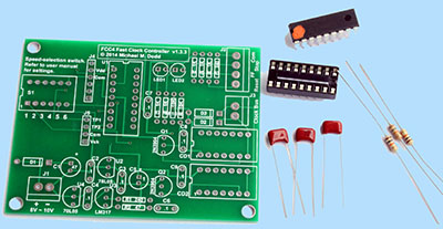
FCC4 Kit
$95.00
This photo shows only a representative assortment of kit parts, not everything that comes in the kit.
Click the Add to Cart button to buy an FCC4 kit.
The FCC4 kit includes a circuit board and all electronics parts for you to assemble.
You provide an 8VDC - 10VDC power supply, optional control switches, and a case if one is desired. Please read the user manual.
|
View Cart to change quantity or check out.
|
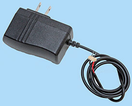
FCC4 Power Supply
$22.00
This is a 9VDC, 1A power supply that will run the FCC4 with up to 15 clocks attached. It comes with a two-pin connector that fits the screw terminal block on the FCC4. Click the Add to Cart button to buy this power supply.
|
|
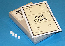
Plastic case with printed panel and standoff bracket for FCC4.
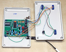
Typical FCC4 installation in the case. The FCC4 is glued to a standoff bracket that is glued to the case bottom.
Switches are on the case top, and connect to the FCC4 with stranded wires from CAT5 Ethernet cable. Jacks for DC power and the clock bus are on one side of the case bottom.
|
Plastic Case for FCC4
$17.50
Must be purchased with an FCC4
Click the Add to Cart button to buy this plastic case for the FCC4. It comes with a printed panel and a standoff bracket to install the FCC4 controller inside.
Switches:
You provide the pushbutton and switches. Here's what they do:
- Power On/Off switch – Switches the adapter's DC voltage to the FCC4.
- Run/Stop switch – Starts and stops the fast clock.
- Normal/Fast Forward switch – Clock runs at the speed set on the FCC4 or at 17:1 speed to rapidly advance to a new time.
- Rset button – With the clock stopped (typically after an op session), pressing this button runs it at 17:1 until it reaches the starting time when power was applied to the FCC4.
Instructions:
- Trim the printed panel to fit inside the shallow depression on case front.
- Use the printed panel as a template to center-punch holes for the switches and button.
- Remove the printed panel, drill the holes.
- Mark and drill holes in case side for 9VDC power and clock bus connectors. Tip: Don't install connectors. Instead cut slots in the side of the case bottom, and connect those wires directly to the FCC4's terminal blocks.
- Glue the printed panel to the case front with spray adhesive such as 3M #77.
- When adhesive is dry, install the switches, button, and connectors. You can use the included 3D-printed flat washers beneath the outer nut to protect the front panel if your switches don't have washers.
- Install the FCC4 in the case bottom using the provided standoff bracket to hold it above the edge ridge. Glue the bracket to the FCC4 corners and the case bottom near the edges.
- Wire the switches, button, and connectors to the FCC4 according to the instructions in the User Manual.
- Final note: The front-panel power switch should be wired between the 9VDC output from your power adapter and the FCC4.
Do not wire 120VAC house power to this switch!
Plug the adapter into an outlet that is powered only while you are operating your model railroad, and switch its DC output to the FCC4.
|
Contact
Updated
February 26, 2025